


New article
Recently updated
Tuning noise-to-track matching parameters

Who is this article for?ANOMS administrators who need to set or improve noise-to-track matching for their monitors.
Administrator access to the ANOMS Noise Analyst Workbench is required.
The performance of noise-event-to-track matching depends on the values of four Location Match parameters: Begin Time Window, End Time Window, Max Altitude and Max Range.
Before you begin
Set and check these parameters carefully whenever a new RMT is installed or a new portable monitor Location is set up. Until you have gained experience in setting them up, ask Ideagen support for assistance.
Setting initial range and altitude values
To set the distance parameters, review flight track data relative to the location of the RMT:
- Use the Query Generator or Operations Browser to display tracks for the different airport operating modes.
- Set the Origin to the new Location and use PCA (point of closest approach) to measure the altitude and ground range to the tracks.
- Ensure that the measurement values are in metres.
- Use your judgement to evaluate which tracks most likely cause noise events at the monitor Location.
- Use the Penetration Gate Analysis (PGA) Graph to check for altitude and range deviations.
To configure the range and altitude parameters:
- Set the range and altitude to the maximum measured value plus 10%.
Note: In general, the range parameter should not exceed 3500 metres and the altitude should not exceed 2500 metres, unless the monitor is more than 10 km from the end of the runway. For monitors within 4 km of the runway end, more typical values would be 1800 metres altitude and 2200 metres range.
Note: The likelihood function for matching is linear, with a value of zero at the Max Range or Max Altitude. An aircraft with a PCA value equal to the Max value has zero probability of being matched to the noise event — this is why the 10% addition to your measured values is needed.
Setting initial time values
The time parameters are relative to the time of maximum noise level of the event (Lmax). All tracks that have a range and altitude within the distance parameters at any time during the time window are considered as possible causes of the noise event. The right values depend on two factors:
- Frequency of arrivals and departures: the time window needs to be short enough that operations do not overlap
- Distance of the aircraft: the time it takes for sound to travel from the aircraft to the noise monitor (approximately 330 metres per second) causes the time of Lmax to fall after the time of the point of closest approach. This is why the end time should usually be a larger value than the begin time
To prepare for setting time parameters:
- Use Replay to review flights going past the monitor Location.
- Determine the time interval between operations for both arrivals and departures.
- Using the previously measured values of slant range at PCA, calculate the sound propagation time.
To set the time parameters:
- Set the begin time somewhere between -11 and -20 seconds, depending on how far away the aircraft are.
Note: For monitors further than 8 km from the end of the runway, the begin time may need to be more negative than -20.
- Determine the end time by adding the sound propagation time to the begin time and changing the sign.
- Keep the total time window less than half the interval between operations.
Reviewing performance and resetting parameters
Once noise data has been collected from the RMT Location and matching has run, review the performance:
- If possible, spend some time at the monitoring Location and observe flights and aircraft noise events.
Tip: This provides insight into the types of flights that cause noise events there.
- Run Replay for at least a one-hour period.
Note: The classification of noise events is colour-coded, so it is simple to spot noise events that should be community or overflight related but are classified as local aircraft events, or vice versa. Replay can run at many times normal speed to make this analysis faster.
- Note any obvious mistakes in classification.
- Use the Browsers to find the tracks associated with the mistakes, measure the PCA values to the monitor Location, and look at the graph of the noise event to confirm it was a typical single-aircraft noise event (its duration and shape are reasonable for a single aircraft).
- Adjust the parameters so the classification error is no longer possible.
Note: For aircraft events classified as community events, increase at least one of the values; for community events classified as aircraft, decrease one or more of the values.
- Adjust as few parameters at one time as possible.
- Manually rerun noise-to-track matching.
- Repeat the review process.
Example airport configuration
The following example shows the settings established for the fixed noise monitors at one example airport (San Jose International). All the monitors are located within 4 km of the end of the runway. The table shows the settings for each monitor, and the figure shows their positions relative to the runways.
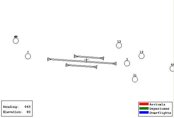
Example airport monitor layout: numbered monitor Locations around the runways
Monitor Location number | Begin Time | End Time | Max Altitude (metres) | Max Range (metres) |
3 | -11 | 18 | 1900 | 2200 |
13 | -13 | 18 | 2200 | 3000 |
19 | -15 | 20 | 2200 | 3400 |
31 | -15 | 20 | 2000 | 3200 |
46 | -12 | 18 | 1800 | 2200 |
7 | -11 | 18 | 1800 | 2200 |